RACO MA Actuator Design 
Main design features
Configurations
ACME versus ball screw
The Modular System
Type Code
Drive Motors
Accessories 

Over Stroke Protection
Actuator in Extreme Cold Environments


RACO Modular Actuator Main Design Features
Electric actuator

Electro-mechanical linear actuators are gaining more and more recognition in the industry as reliable, strong and environmentally friendly components to replace hydraulic and pneumatic cylinders. With more than 50 years of experience and unique patented features the RACO Electric Linear Actuator is the standard in the industry. The most important advantages of RACO Electric Linear Actuator are the RACO motor, specifically developed for actuator duty, and the patented nut system. The RACO motor, which does not have a breakdown torque, provides a soft acceleration of loads. In connection with the patented hammerblow bolt in the nut housing, the RACO motor produces a breakaway thrust much larger than the nominal thrust. RACO Electric Cylinders are economical to operate, since they usually work for just a few seconds and consume energy only during that short period. Contrary to hydraulic and pneumatic systems, no energy is consumed during idle periods. 

The size of the drive motor can be kept very small due to high efficiency of the electromechanical system. Feeding the electrical energy through cables is easy and non-contaminating. Leaking and freezing problems, which occur in other systems, are not probable. High and freezing temperatures, dust, humidity, and vibrations are normal operating conditions for RACO Electric Linear Cylinders. Even under extreme conditions they work with precision and reliability, proven by their wide range of applications throughout all industries. They operate ladle pre-heaters in steel mills and position parabolic antennas for space applications. They are even used in explosive environments in the chemical industry as well as in coal mining. The electro-mechanical RACO system fulfills the highest requirements for cleanliness and environmental protection, even for applications in the food industry.

 
Download Precision in Motion Video Clip
AVI  file - 40,050 KB


Return to Top
of Page

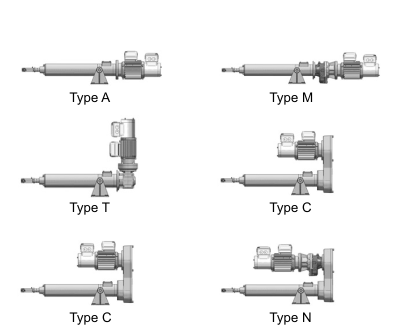
DRIVE CONFIGURATIONS


In-line Drive Configuration
Type "A" - Direct coupled motor

 In-line Drive Configuration
Type "M" - Inline Gear Motor


Drive Parallel to Thrust Tube
Type "C" - Motor / Timing Belt driven

Drive Parallel to Thrust Tube
Type "N" - Motor / Timing Belt driven


Right Angle Drive Configuration
Type "T" - Right angle Gear Motor

Return to Top
of Page

ACME SCREWS VERSUS BALL SCREWS

The rotational energy, produced by the electric motor, will be converted into a linear movement by the ACME or Ball Screw installed within the thrust unit. ACME screws are typically self-locking. Based on a low lead selection and the resulting large surface area between the nut and the screw provides a robust power transfer assembly and a high capability for shock loading. Static loads, which can always be higher than the nominal thrust, can be safely maintained in all positions. Different leads for the screw can be easily produced to influence the behavior of power transfer between the motor and the thrust rod which will change the rod speed, thrust capability and efficiency. Higher leads, however, do not have the self-locking feature, so the actuator will be equipped with an electro-magnetic brake to maintain position.
Inherent to the Ball Screw design, the contact between the ball nut and the ball screw are point to point connections provided by a number of re-circulating high precession balls. The rolling friction of the balls is extremely low compared to the sliding friction of the ACME screw. Therefore the power transfer between the rotating shaft of the electrical motor and the linear thrust at the ball nut has an efficiency higher then 95%. The benefits include: a higher duty cycle, longer lifetime, extended ambient temperature range, smaller drive motor, starter and infrastructure due to the high efficiency,  and an extremely high position accuracy  and repeatability
. In combination with a spring package, counter weight or other means which would provide a source of stored energy, a defined failsafe position can be obtained in case of a electrical power loss or other mechanical interruption or failure.

Return to Top
of Page

THE RACO MODULAR SYSTEM
 

Download The Modular Actuator System Overview
PDF  file - 1934 KB


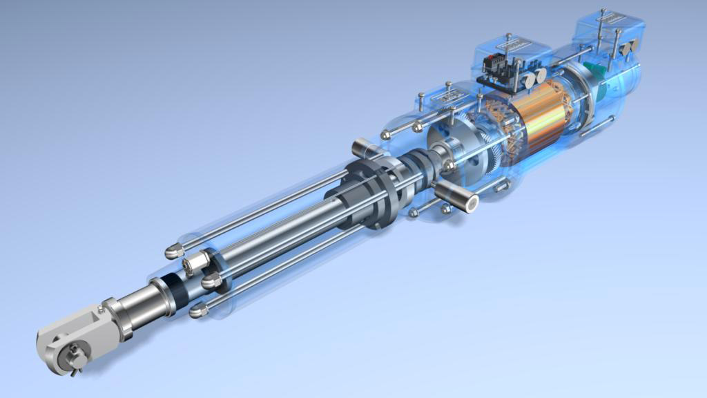
1. Thrust unit with self-locking ACME screw or non-locking ball screw, to convert rotational into linear movement. Shield tube made of aluminum for sizes 3-5, steel for larger sizes, with optional interior paint coating for tropical- proof requirements. Thrust tubes made of stainless steel thru size 6, with hard chromium plating on larger sizes. Front cap with seal and extra long bushings to withstand small lateral forces. Available with double and special high or low temperature seal.

2. The RACO motor is totally enclosed, has a high starting torque and provides a smooth acceleration of loads. Standard is insulation Class F, TENV and torque characteristics better than NEMA D. Motor windings are double impregnated under vacuum. For high rod speeds, motors are directly coupled to the cylinder power screw with resilient or no backlash coupling.

3. Coupling housing with large lateral accessory box instead of rear accessory housing. (Necessary if overall length must be reduced, if handwheel is installed behind motor, or if drive motor other than RACO is used.) In addition to stroke limit switches and feedback potentiometers we can incorporate:
Blinking signal light to indicate cylinder motion.
Pulse transmitter for electronic thrust overload protection.
Pulse transmitters for digital positioning control.

4. Drive housing for cylinder type “C” or “N” (timing belt driven) for shortest overall length. In addition to a direct ratio of 1:1, step-up and step-down ratios 1:1.5, 1:2.0, and 1:2.5 are possible.

5. Parallel gear to reduce motor revolutions for low linear speeds, and boost the motor torque.

6. Right angle gear to reduce motor revolutions for slow speeds, and to reduce overall length.

7.   Electro-magnetic brake type “L” (applies braking force when power is off) is required with a ball screw or a high-lead acme screw, neither of which is self-locking. Exact positioning applications also require this brake. Depending on the application, the brake can be wired for a short, medium, or fast reaction time Electro-magnetic brake type “B” (applies braking force when power is on) for safety applications requiring the cylinder to back drive to a desired safe position in case of a power failure. Counterweights or springs must be used in connection with non-locking ball screws to provide back driving force.

8. Rear accessory housing for stroke limit switches, feedback potentiometer, and position emitter.

9.  Many types of customer specified motors such as AC, DC, servo, stepping motors and gear motors are adaptable.

10. Lateral accessory housings can be used on all cylinders. All the available accessories can be mounted in these housings.

11. Solid handwheel is available for manual operation/adjustment of the cylinder. Optional mechanical and electrical disengaging mechanisms are also available. All accessories are installed in the lateral accessory housing when the cylinder is furnished with a hand wheel.

Return to Top
of Page

 TYPE CODE

Return to Top
of Page

WIDE VARIETY OF MOTORS

The wide range of drive motors for different operating conditions and enclosures offers the optimum solution for each application. The flexibility of the RACO Compact System permits the use of commercial motors to complement the wide variety of RACO provided motor solutions.

Return to Top
of Page

VARIETY OF ACCESSORIES

A wide range of control equipment is available for the RACO Compact Actuators, such as limit switches, starters, relays, potentiometers, inductive transmitters, non-contact position / speed sensors and controllers, position control and feedback devices designed with a high degree of reliability. Analog and digital feedback devices as well as adjustable limit switches are typically housed in sealed and protected compartments integrated into the actuator.

Return to Top
of Page

Over Stroke Protection

In critical applications, where an accidental over stroking of the actuator is possible due to malfunctioning of control equipment or human errors, elastomer impact shock absorbing rings can be installed at the physical stroke limits. These high impact resilient absorbing rings are installed on the front cap for the extended position, and  on the bearing block for the retracted position of the actuator. The kinetic energy of the power screw and the breakdown torque of the motor will be transformed into an elastic deformation of the absorbing ring. This will protect the power screw form an otherwise possible catastrophic crash.


Download Over Stroke Protection Brochure
PDF  file - 541 KB

Return to Top
of Page

Actuator in Extreme Cold Environments

For extremely cold or high humidity environmental conditions RACO has developed a number of actuator component heating solutions. These solutions are tailored to the environmental conditions, the application specific functions and the optimal resulting actuator configuration. The below PDF flyers give a brought overview of different heating methods. The following examples are presented:
          - Strip heating of enclosed compartments like limit switches, brake housing;
          - Low voltage, low frequency heating of the motor windings;
          - On board control panel heating;
          - Resistive Motor winding heater and electronic brake heater circuits;


Download Actuator Brake Heater Brochure
PDF  file - 128 KB

Download Actuator Motor Heater Brochure
PDF  file - 124 KB


Download Actuator Panel Heater Brochure
PDF  file - 135 KB

Download Commercial Actuator Motor & Brake Heater Brochure
PDF  file - 135 KB


Return to Top
of Page